-
Products related to categories: servo, frequency conversion, HMI, driver, distributed DCS, IPC (PC bus industrial computer), PLC (programmable control system), DCS (distributed control system), FCS (field bus system), robot and other products and technical services.
-
Applications: Wind energy, automobile, ship, transportation, manufacturing, aviation, petroleum, natural gas, thermal power, thermal power, nuclear energy, steel, metallurgy, mining, power and other industries
-
Controller PLC\Robot servo drive Electro-hydraulic servo valve\DCS system/Distributed control systemSystem rack\Communication adapter\Analog output\Analog input\
-
\Multi-meter energy meter\Ignition\circuit board\Crimp terminal\Electric ac drive\Low voltage DC power module\Electro-hydraulic\servo valve\Automatic control system\exchange\Network communication module
controller\Processor module\dynamo\Electric machine\Servo drive\Touch screen\Input/output module\Water treatment monitoring system\Automobile\manufacturing system\Thermoelectric control system\ -
Digital output\Digital input\Mechanical protection system\High speed CPU
-
Electric power system\Chemical testing system\Petroleum control system\Tension monitoring system
-
DCS Distributed\control system\Steel control system\Steam\turbine system\Power generation system\
-
Thermal power generation system\Wind power system\Medium and high voltage frequency\conversion system\Precision motion system\Programmable control system\


- AMAT
- KUKA
- BASLER
- ELMO
- IBA
- GALILMC
- Ormec
- Beckwith
- Valmet Metso
- Mitsubishi
- VMIC
- Hitachi
- AEROTECH
- DEIF
- Micro Innovation
- WATLOW
- MATROX
- SYMAP
- Praxis Automation
- UNIOP
- ZYGO
- ROLLS-ROYCE
- YOKOGAWA
- SAIA
- Vibro-Meter
- MEGGITT
- RELIANCE
- REXRTOH
- KONGSBERG
- Kollmorgen
- MOTOROLA
- NI
- Toshiba
- REXROTH
- MITSUBISHI
- PROSOFT
- TRIPLEX
- KROHNE
- KOKUSAI
- MOOG
- ROCKWELL
- Industrial robot
- PLC
- Inverter
- motor
- Industrial switch
- Instrument and meter
- Industrial power
- Machine tool
- Technical service
- Other electrical
- Oil equipment
- Mining equipment
- Triconex
- Woodward
- YASKAWA
- SST
- Servo system
- Siemens
- schneider
- Ship control equipment
- Steam turbine equipment
- sensor
- ALSTOM
- ABB
- ABACO
- A-B
- ADLINK
- BENDER
- B&R
- Bently
- Control cabinet
- CAMERON
- Chemical equipment
- Cement equipment
- CNC
- COGNEX
- CTI
- contactor
- CAMERON
- DCS
- Drive system
- EATION
- EMG
- EMERSON
- EPRO
- Engineer
- Electrical system
- Electric power equipment
- FIREYE
- ENTERASYS
- FOXBORO
- GE ALSTOM
- GEC ALSTHOM
- Honeywell
- HIMA
- HP
- Hardware accessories
- HMI
- Hirschmann
ICS Triplex AADvance控制器处理器冗余模块
ICS Triplex AADvance控制器处理器冗余模块
Introduction
The TrustedTM TMR Expander Interface module resides in the TrustedTM Controller Chassis and provides the ‘master’ interface between the Inter-Module Bus (IMB) in the Controller Chassis and the Expander Bus. The Expander Bus allows multiple chassis systems to be implemented using UTP cable connections whilst maintaining the fault tolerant, high bandwidth IMB capabilities. The module provides fault containment for the Expander Bus, the module itself and the IMB in the Controller Chassis, ensuring that the effects of these potential faults are localised and system availability maximised. The module is fault tolerant with HIFT TMR architecture. Comprehensive diagnostics, monitoring and testing provide rapid fault identification. Hot standby and module spare slot configurations are supported, allowing automatic and manual repair strategies.
Features
• Triple Modular Redundant (TMR), fault tolerant (3-2-0) operation
• Hardware Implemented Fault Tolerant (HIFT) architecture
• Dedicated hardware and software test regimes which provide very fast fault recognition and response times
• Automatic fault handling without nuisance alarming
• Hot replacement
• Front panel indicators that show module health and status.
• T2V Certified IEC 61508 SIL 3
Notice
The content of this document is confidential to ICS Triplex Technology Ltd. companies and their partners. It may not be given away, lent, resold, hired out or made available to a third party for any purpose without the written consent of ICS Triplex Technology Ltd.
This document contains proprietary information that is protected by copyright. All rights are reserved. Microsoft, Windows, Windows 95, Windows NT, Windows 2000, and Windows XP are registered trademarks of Microsoft Corporation.
The information contained in this document is subject to change without notice. The reader should, in all cases, consult ICS Triplex Technology Ltd. to determine whether any such changes have been made. From time to time, amendments to this document will be made as necessary and will be distributed by ICS Triplex Technology Ltd. Information in this documentation set may be subject to change without notice and does not represent a commitment on the part of ICS Triplex Technology Ltd.
The contents of this document, which may also include the loan of software tools, are subject to the confidentiality and other clause(s) within the Integrator Agreement and Software License Agreement. No part of this documentation may be reproduced or transmitted in any form or by any means, electronic or mechanical, including photocopying and recording, for any purpose, without the express written permission of ICS Triplex Technology Ltd.
Disclaimer
The illustrations, figures, charts, and layout examples in this manual are intended solely to illustrate the text of this manual.
The user of, and those responsible for applying this equipment, must satisfy themselves as to the acceptability of each application and use of this equipment.
This document is based on information available at the time of its publication. While efforts have been made to be accurate, the information contained herein does not purport to cover all details or variations in hardware or software, nor to provide for every possible contingency in connection with installation, operation, or maintenance. Features may be described herein which are present in all hardware or software systems. ICS Triplex Technology Ltd. assumes no obligation of notice to holders of this document with respect to changes subsequently made.
ICS Triplex Technology Ltd. makes no representation or warranty, expressed, implied, or statutory with respect to, and assumes no responsibility for the accuracy, completeness, sufficiency, or usefulness of the information contained herein. No warranties of merchantability or fitness for purpose shall apply.
Description
Overview
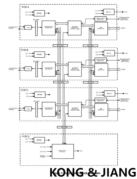
The TMR Expander Interface is a fault tolerant design based on TMR architecture arranged in a lockstep configuration. Figure 1 shows, in simplified terms, the basic structure of the TMR Expander Interface. The module has three main fault containment regions (FCR A, B and C). Each of the main FCRs contains interfaces to the Expander Bus and Inter-Module Bus (IMB), an active/standby interface to the other TMR Expander Interface in the chassis, control logic, communications transceivers and power supplies. Communication between the module and the TMR Processor is via the IMB on the backplane of the Controller Chassis. The IMB provides fault tolerance and high bandwidth communications between the Interface Modules and the TMR Processor. All transactions are voted, localising faults to the IMB should they occur. Communication between the Interface Module and the TMR Expander Processor in the Expander Chassis is via the Expander Bus. The Expander Bus is triplicated, point-to-point architecture. Each channel of the Expander Bus comprises separate command and response media. Voting is provided at the Expander Bus Interface to ensure that cable faults are tolerated, and the remainder of the Expander Processor operates in a fully triplicated mode, even in case of cable faults occurring. A fourth FCR (FCR D) provides the non-critical monitoring and display functions and is also part of the inter-FCR Byzantine voting structure. Isolation is provided between FCRs wherever interfaces are required, to ensure that faults can not propagate between them.
Power Distribution The TMR Expander Interface Module derives its internal voltages from dual redundant +24V dc power supplied via the module connector from the TrustedTM Controller Chassis backplane. Each FCR derives the required supplies independently.
Module Installation
The Expander Interface Modules may reside in any of the I/O slots within the Controller Chassis. The modules are installed in pairs with the left-hand module occupying an odd numbered slot. The Expander Interface must NOT be installed in these other module locations, as this may cause damage to the module. The two Interface slots must be interconnected using the Expander Interface Adaptor Unit T8312. The Expander Interface Modules are connected to the Expander Processor Modules by the Expander Interface Hot Link Cable TC-301 via the TrustedTM Expander Interface Adaptor Unit T8312. The connection to remote Expander Chassis is via the TrustedTM Fibre Optic Tx/Rx Unit using the Expander Interface Adaptor to Fibre Tx/Rx Unit (Remote Expanders) Cable TC-302.
Module Insertion and Removal CAUTION: THE MODULE CONTAINS STATIC SENSITIVE PARTS. STATIC HANDLING PRECAUTIONS MUST BE OBSERVED. SPECIFICALLY ENSURE THAT EXPOSED CONNECTOR PINS ARE NOT TOUCHED. UNDER NO CIRCUMSTANCES SHOULD THE MODULE HOUSING BE REMOVED. Before installation, visually inspect the module for damage. Ensure that the module housing appears undamaged and inspect the I/O connector at the back of the module for bent pins. If the module appears damaged or any pins are bent, do not install the module. Do not try to straighten bent pins. Return the module for replacement. Ensure that the module is of the correct type. Record the module type, revision and serial number of the module before installation. If the module is to reside in a new chassis, or the system is being configured for the first time, ensure that the chassis address has been set correctly before installing the modules. See Controller Chassis Product Description (PD-8100) for further details. To install the module: 1. Ensure that the cable assembly is correctly located. 2. Release the ejector tabs on the module using the release key. Ensure that the ejector tabs are fully open. 3. Holding the ejectors, carefully insert the module into the intended slot. 4. Push the module fully home but pressing on the top and bottom of the module fascia. 5. Close the module ejectors, ensuring that they click into their locked position.
Module Replacement
The replacement module must be inserted in to the vacant processor slot, ensuring that the module is correctly located and the ejector tabs are closed (see 2.2). The newly installed module will perform its power-up sequence. Ensure that the LED indicators on the newly installed module are as follows: LED 1 Healthy A Steady Green LED 2 Healthy B Steady Green LED 3 Healthy C Steady Green If the original module has reported faults, the TMR Processor may automatically initiate the changeover to the newly installed module. Manual changeover may be initiated either using the ejector tabs on the original module or using commands via the diagnostic interface. To initiate the changeover using the ejector tabs use the following sequence: 1. Release both the top and bottom ejector tabs on the original module using the ejector release tool. DO NOT remove the module. 2. Wait until the original module indicates that it is in the standby mode of operation and the newly installed module is in the active mode. 3. Remove the original module.
- User name Member Level Quantity Specification Purchase Date
- Favorable :
-


Delivery:
Warranty:
All our products are covered by our own warranty.
Payment method:
Quick Quote: Receive price and availability today!


1, the use of voltage regulator or transformer: the voltage regulator can automatically adjust the output voltage, keep in the set stable range, suitable for all kinds of electronic equipment. Transformers can rise and fall voltage, suitable for specific voltage requirements of electrical appliances.
2, Install UPS uninterruptible power supply: Uninterruptible power supply (UPS) can provide a stable power supply for the equipment when the grid voltage is unstable or power failure, while protecting the equipment from voltage fluctuations.
3, regular inspection of the power line: aging or damaged power lines may lead to voltage instability, regular inspection and maintenance is necessary.
4, the use of qualified power cables and sockets: the use of national standards, quality qualified power cables and sockets, can reduce the voltage fluctuations caused by cable problems.
5, avoid using sensitive equipment when the voltage is unstable: for some equipment that is particularly sensitive to voltage fluctuations, such as precision instruments, computers, etc., should try to avoid using when the voltage is unstable.
6, consult professionals: For the problem of voltage instability, you can contact the power supply department or professional electricians for inspection and treatment.
7, understand the local power supply situation: in some areas, the voltage instability may be due to the grid load is too large or grid facilities caused by aging, understanding the situation can take corresponding measures.
8, purchase voltage protection equipment: there are some protection equipment specifically designed for voltage instability on the market, such as voltage protectors, overvoltage protectors, etc., can automatically power off protection equipment when the voltage is abnormal.
Taking appropriate measures to protect electrical equipment can not only extend the service life of the equipment, but also ensure the safety of use and avoid safety accidents such as fire caused by voltage instability.
Replacing an electrical equipment unit in a plant is a complex task that requires careful planning and execution to ensure safety and minimize downtime. Here is a general step-by-step guide on how to replace electrical equipment in a plant:
-
Pre-Planning:
- Identify the specific equipment that needs to be replaced and understand its function within the plant.
- Purchase or order the new equipment, ensuring it is compatible with the existing system.
- Review the manufacturer’s installation and operation manuals for the new equipment.
- Develop a detailed replacement plan, including a timeline, required materials, and safety procedures.
- Notify all relevant personnel and departments about the planned downtime and replacement.
-
Safety Precautions:
- Ensure that all safety protocols are in place before starting any work.
- Lock out/tag out (LOTO) the equipment to be replaced to prevent accidental energization.
- Wear appropriate personal protective equipment (PPE), such as safety glasses, gloves, and hard hats.
-
Shutdown Procedures:
- Follow the plant’s standard shutdown procedures to safely stop the equipment and isolate it from the power source.
- Double-check that the equipment is de-energized and all energy sources are disconnected.
-
Disconnection:
- Disconnect all electrical connections to the equipment, including power cables, control wires, and grounding cables.
- Label all disconnected cables and connections for proper reinstallation.
-
Removal of Existing Equipment:
- Carefully remove the old equipment, which may involve disassembling components or using lifting equipment.
- Dispose of the old equipment in an environmentally responsible manner, following local regulations.
-
Installation of New Equipment:
- Position the new equipment in place, ensuring it aligns with existing connections and infrastructure.
- Reconnect all power, control, and grounding cables, referring to the installation manuals and diagrams.
-
Testing and Commissioning:
- Perform a visual inspection to ensure all connections are correct and secure.
- Gradually power up the new equipment and conduct functional tests to ensure it operates correctly.
- Perform any necessary calibration and adjustments.
-
Documentation:
- Update all relevant documentation, including maintenance logs, schematics, and operating procedures.
- Record the details of the replacement, including dates, personnel involved, and any issues encountered.
-
Training:
- Provide training to plant personnel on the operation and maintenance of the new equipment if necessary.
-
Startup:
- Restart the plant processes and monitor the new equipment closely to ensure it performs as expected.
Throughout the process, it’s important to work closely with a team that includes electrical engineers, technicians, and maintenance staff. Communication is key to a successful equipment replacement. Additionally, always adhere to local electrical codes and standards to ensure compliance and safety. If the task is beyond the expertise of in-house staff, consider hiring a professional contractor experienced in industrial electrical work.
Obtaining industrial automation programming software typically involves the following steps:
-
Identify Your Needs:
- Determine the specific automation tasks you need to perform and the type of equipment (such as PLCs, PACs, HMIs, or industrial PCs) you will be programming.
-
Research Software Options:
- Look for software that is compatible with the hardware you are using or planning to use.
- Consider the industry standards and what is commonly used for your type of application.
- Read reviews, forums, and case studies to learn about the experiences of others with different software packages.
-
Contact Equipment Manufacturers:
- Many automation hardware manufacturers provide their own programming software, which is often optimized for their products.
- Visit the manufacturer’s website or contact their sales or support team to inquire about the software options available.
-
Purchase or Download:
- For proprietary software, you may need to purchase a license from the manufacturer or an authorized reseller.
- Some software may be available for download directly from the manufacturer’s website, either as a full version or a trial version.
-
Academic or Evaluation Versions:
- If you are a student or educator, you might be eligible for educational discounts or free versions of the software.
- Some companies offer evaluation versions of their software for a limited period, allowing you to test it before purchasing.
-
Open Source Options:
- Consider open-source software, which is often free to use and can be modified to suit your needs. However, open-source software may not come with the same level of support as proprietary software.
-
Licensing:
- Understand the licensing agreement for the software. Some software requires a one-time purchase, while others may require annual subscriptions or per-use fees.
-
Training and Support:
- Look into the availability of training resources, such as tutorials, manuals, and online courses, to help you learn how to use the software effectively.
- Consider the level of technical support provided by the software vendor, which can be crucial for troubleshooting and resolving issues.
-
Legal and Compliance:
- Ensure that the software complies with any industry regulations or standards that apply to your operations.
- Make sure you have the legal right to use the software in your country or region.
-
Installation and Setup:
- Follow the installation instructions provided by the manufacturer.
- Configure the software according to your system requirements and the hardware you are using.
Here are some common ways to obtain industrial automation programming software:
- Direct from the Manufacturer: Order directly from the company that produces the software.
- Authorized Dealers: Purchase from authorized dealers or distributors who have been granted the right to sell the software.
- Online Marketplaces: Some software may be available for purchase on online marketplaces, but always ensure the seller is reputable and authorized.
- Volume Licensing: For large organizations, there may be options for volume licensing that can reduce costs.
Remember to keep your software updated to benefit from the latest features and security patches. Also, ensure that you have the necessary backup and recovery procedures in place to protect your programming work.
1.Consult local manufacturers and get quotations
2. Consult the supplier selling this product
3. To ensure the equipment operates faster, request maintenance services from the maintenance provider.
4. Products that can be used with the ordering function functioning properly.
1、Consult the local manufacturer to see if it is still possible to place another order. The price is definitely expensive.
2. Request repair services from the maintenance provider. This is the fastest way to get the device running.
3. Seek upgraded alternative products. The equipment may not be suitable. It might be necessary to modify more supporting equipment.
4. Products that can be used with the ordering function functioning properly. (You can entrust us to search.)
2. After being inspected by professional engineers, it is determined whether it can be replaced.
3. After professional technical transformation or the installation of intermediate relay equipment.
On the brand's technical website or technical hotline.
-
The company is organizing a trip to Yekaterinburg, a beautiful city
-
Bender IRDH265 IRDH365 isolated power
-
Allen-Bradley IntelliVAC™ Contactor Control Module Bulletin 1503VC
-
Foxboro Software Defined Automation - The first open, software-defined DCS | Schneider Electric
-
RELIANCE PSC7000 PROGRAMMABLESERVO CONTROLLER
-
DISCO Corporation Precision wafer processing equipment
-
JamesburyTM compact rack andpinion pneumatic actuatorValv-PowrTM VPVL series model D
-
VACON One of the world's leading AC variable frequency drives
-
PCH DIGITAL WINDTURBINE STRUCTURAL VIBRATION MONITOR PCH 1026
-
Valmet secures a major automation contract
-
Hardy Process Solutions 1756 Weigh Scale Module rockwell
-
ADVANTEST R6144 DC Voltage/Current Generators/Calibrators
-
MOTOROLA ACE3600 Advanced Control Equipment
-
Woodward EM-80/EM-300 Actuator system
-
Rockwell Kinetix 6000 Integrated Axis Module
-
Honeywell ControlEdge™ HC900 controller
-
GE MULTILIN G60 Generator Protection System
-
Vibro-meter VM600 Comprehensive Machinery Protection and Condition Monitoring System
-
Honeywell System 57 Gas Detection Control System: Comprehensive Overview
-
What are the models in the Abaco single-board computer motherboard series?
-
Comprehensive Guide to Rockwell (Allen-Bradley) PLC Seri
-
ABB AC 800M Distributed Control System Controller Series
-
stucke GROUP SYMAP Digital Protection Relays
-
PACSystemsTM RSTi-EP Controllers EPSCPE100 115 EPSACC001
-
ALSTOM Converteam ALSPA MV3000 Delta Controller MVC3001-4003 MVC3001-4013
-
GE Multilin MII Family Modular Microprocessor Family
-
Elmomc Gold Tuba Digital Servo Drive Installation Guide EtherCAT and CAN
-
GE Multilin 350 Intuitive and Innovative Feeder Protection
-
Yokogawa AIP830-111 Operation Keyboard for Singleloop Operation
-
TRACO POWER Industrial Power Supplies TIS
-
ABB SPAU 341 C Voltage regulator SPAU341C How to set it up?
-
KONGSBERG RMP420-Remote Multipurpose Input/Output
-
ELAU PacDrive Controller C200/C200 A2
-
Schneider ELAU PacDrive Controller C400/C400A8
-
Schneider ELAU PacDriveTm Servo Drive MC-4
-
GE Grid Solutions Kelman Transport X² Portable Onsite DGA
-
BASLER DECS-200-2L Digital Excitation Control System
-
BASLER DECS-250E Digital Excitation Control System
-
ABB NSB204-502W motion control products NextMove
-
Bently 2300/20 and 2300/25 2300 Vibration Monitors
-
GE MIGII Legacy Generator Protection System
-
Siemens Teleprotection for high-voltage lines SWT3000
-
ABB Synchrotact-5200 Synchronizing and Paralleling devices and systems
-
ABB REF630 Feeder Protection and Control
-
MOTOROLA MVME2400 Series TM VME Processor Modules
-
SARTORIUS MDB-8E MDB Metal detectorsr 85-264V
-
ABB Symphony Plus S+ Turbine: Auto Synchronizer Module AS800
-
ABB I/O Systems - S900 I/O Ability™ System 800xA®
-
ABB S800 I/O Modules and Termination Units
-
ABB DCS880 Drives (20 ... 5200 A) converter modules
-
Rexroth Indramat Bosch Digital axis control HNC100
-
ABB Bailey DCS Connections Network 90,® Net 90® and INFI 90®
-
ABB Ability™ Symphony® Plus MR Series
-
GE PACSystems™ RX3i Controllers Product
-
ABB Symphony Plus SD Series HPC800 controller
-
ABB AC800M Controller Hardware System
-
ABB AC800M PROFIBUS DP Installation System
-
ABB Freelance 800F AC800F Control systems
-
ABB Compact control system replaces PLC AC700F
-
ABB System 800xA Operations Power and productivity
-
abb Triguard SC300E 3BNP004720R101 TMR Safety Products
-
ABB Distributed busbar protection REB500
-
Automation System ABB Procontic T200
-
ABB PCS8000 AC Excitation SYSTEM DRIVES
-
ABB drives MEGADRIVE-LCI 2 to 150 MW
-
ABB Advant® Controller 450 proven process controller
-
ABB Advant® Master S100 I/O system
-
ABB Freelance 2000 Contrans Instruction Freelance2000
-
ABB MEASUREMENT & ANALYTICS Advance Optima and EasyLine
-
ABBEL3020 EL3040 EasyLine Continuous Gas Analyzers Models
-
GE Digital Energy 489 Generator Management Relay Multilin
-
Woodward easYgen-3000 Genset Control Unit
-
ABB Dynamic braking DC Drive Up to 960 A, 600V DC EHDB
-
ABB DCS800 Drives (20 A to 5200 A) Control system
-
GE HYDRAN® 20li SystemTechnical Specifications H201TI
-
Tricon™ v9–v11 Systems triconex
-
ABB DCS600 Thyristor Power Converters DC Drive Systems 25 to 5150 A MultiDrive
-
ABB BSD servo system product
-
ABB Advant Controller 110 Open Control System
-
ABB Crane motion controller ASTAT® 25-2000 A 380-690 V
-
ABB Advant Controller 210 Advant® OCS Open Control System
-
ABB Advant Fieldbus 100 AF100 Control system
-
ABB Advant Controller 250 Advant® OCS Open Control System
-
Abaco VR12, VP12 6U VME Single Board Computer
-
ABB GBU72 GRID BREAKER UNIT 3BHE055094R0002 PCS6000 PRODUCT FAMLIY
-
ABB Advant Controller 70 Open Control System
-
ABB ACS800-107 Cabinet Inverter Unit (1.5 to 5600 kW)
-
ABB ACS800-01/U1 drive unit
-
PRAXIS-Automation
-
Schneider Modicon Quantum automation platform Unity Pro standard CPUs
-
ABB NGC8206 Natural Gas Chromatograph Dual Unit
-
EMERSON FloBoss™ S600+ Flow Computer unit
-
SIEMENS SGT6-2000E Turbine power generation equipment series
-
ALSTOM Converteam Comprehensive Brand Overview
-
WATLOW CLS200 Communications Specification
-
ABB KOFA MEDIUM VOLTAGE PRODUCT Indoor current transformers
-
ABB Relion® 670 series Transformer protection RET670 Pre-configured
-
GE PACSystems RX7i PLC UNIT
-
ABB Feeder Protection Relay REX 521 REX521
-
REXROTH ECODRIVE PPC Drive Controllers
-
UniOP UniOP eTOP307 HMI touch unit
-
ABB ASTAT® Product Overview
-
AMAT (Applied Materials) an overview
-
What industrial automation equipment systems are needed for thermal power plants?
-
ABB PGC2007 PGC5007 Total Sulfur Analyzer Operatio
-
ABB Sample Gas Cooler SCC-C
-
ABB wind turbine converters PCS6000, full power converter, up to 15 MW
-
AEROTECH Ndrive Series Digital Servo Amplifiers
-
AEROTECH Ndrive CP Hardware Ndrive Series Digital Servo
-
Molex SST-PB3-VME-1 and SST-PB3-VME-2 interface cards
-
Woodward EPG Electrically Powered Governor Models 512/524 and 1712/1724
-
ABB AC31 PLCs and previous series
-
ABB ACV700 Frequency Converters Discontinued spare parts
-
ABB Advant Controller 400 series DCS
-
ABB M2M MODBUS 2CSG299893R4052 2CSG299893R40 Network analyser
-
Electric tricycle pull goods home pick up children with shed heavy king power battery car
-
ABB MNS iS Motor Control Center MNS iS Interface Manual MLink
-
ABB 670 Advanced voltage control integrated control unit for transformer substation HITACHI
-
ABB Horizontal Measuring PFTL 101
-
Metso maxPAC Input/Output Sub system
-
RELIANCE VZ3000 200-230 VAC Dedicated Type and 200-230 VAC/380-460 VAC Common Type Drive
-
ORMEC Generation III DC DIVER
-
ABB Relion® 615 series Quick Start Guide
-
Yokogawa FIO System Overview Installation to Make I/O Modules Dual-Redundant
-
Ovation™ Power Supply System 5X00785G09
-
ABB Company Profile
-
AMAT Applied Materials Company profile
-
MEERSON A6370 Overspeed Protection Monitor


All new products and surplus products of the industrial intelligence industry, as well as the discontinued products of the original manufacturers. We are not an authorized distributor or representative of any of the above manufacturers (except for brand authorization). The trademarks, brand names and brands appearing in this agreement are the property of their respective manufacturers.
COPYRIGHT© 2003-2026 Copyrighted

Phone(WeChat/Whatsapp)
+086-181 4410 0983
No 1134 Jimei North Road,
Hong Kong Office:
Guan Tang District, Hong Kong,
