-
Products related to categories: servo, frequency conversion, HMI, driver, distributed DCS, IPC (PC bus industrial computer), PLC (programmable control system), DCS (distributed control system), FCS (field bus system), robot and other products and technical services.
-
Applications: Wind energy, automobile, ship, transportation, manufacturing, aviation, petroleum, natural gas, thermal power, thermal power, nuclear energy, steel, metallurgy, mining, power and other industries
-
Controller PLC\Robot servo drive Electro-hydraulic servo valve\DCS system/Distributed control systemSystem rack\Communication adapter\Analog output\Analog input\
-
\Multi-meter energy meter\Ignition\circuit board\Crimp terminal\Electric ac drive\Low voltage DC power module\Electro-hydraulic\servo valve\Automatic control system\exchange\Network communication module
controller\Processor module\dynamo\Electric machine\Servo drive\Touch screen\Input/output module\Water treatment monitoring system\Automobile\manufacturing system\Thermoelectric control system\ -
Digital output\Digital input\Mechanical protection system\High speed CPU
-
Electric power system\Chemical testing system\Petroleum control system\Tension monitoring system
-
DCS Distributed\control system\Steel control system\Steam\turbine system\Power generation system\
-
Thermal power generation system\Wind power system\Medium and high voltage frequency\conversion system\Precision motion system\Programmable control system\
-
Singapore New Energy Corporation
-
Geylang Bahru Industrial Estate
-
การทางหลวงแห่งประเทศไทย
-
American Petroleum Group
-
Indian shipping works
-
Pakistan Gas Company
-
Russian Automotive Industry Corporation
-
Brazilian Mining Company
-
Bangladesh Hydro power Plant
-
Egyptian Iron and Steel Manufacturing Co
-
Groupe d’exploitation du métro français
-
Für meinen vater
-
Mongolia Wind Farm
-
Empresa venezolana de procesamiento de petróleo
-
alibaba
-
Sichuan Huayingshan Power Plant
-
Huadian Datong Power Plant
-
Guodian Shuangyashan Power Generation Co., Ltd.
-
Baosteel Group Xinjiang Bayi Steel Co., Ltd.
-
Guodian Changzhou Power Plant
-
Xingtai Iron and Steel Co., Ltd.
-
Guodian Fee County Power Generation Co., Ltd.
-
Yangzhou Second Power Plant
-
Sichuan Jintang Power Plant
-
Xingcheng Special Steel Co., Ltd.
-
Quzhou Yuanli Metal Products Co., Ltd.
-
Zijin Mining Group
-
(Bangladesh) Metro Construction Company
-
WuHan steel co., ltd.
-
MaAnShan steel co., ltd.
GE AT868 AquaTransrmUltrasonic Flow Transmitter
GE AT868 AquaTransrmUltrasonic Flow Transmitter
![]()
To ensure safe and reliable operation of the Model AT868 Flowmeter,
the system must be installed and programmed in accordance with the
guidelines established by GE Infrastructure Sensing engineers. Those
guidelines, explained in detail in this chapter, include the following
topics:
• Unpacking the Model AT868 system
• Selecting suitable sites for the electronics enclosure and the
flowcell/transducers
• Installing the flowcell/transducers
The Model AT868 may be ordered for operation with power inputs of
85-265 VAC or 12-28 VDC. The label on the side of the electronics
enclosure lists the meter’s required line voltage and power rating. The
fuse size is listed on label located under the fuse. Be sure to connect
the meter only to the specified line voltage.
Wiring Std 0/4-20 mA
Analog Outputs
The Model AT868 flow transmitter has one isolated 0/4-20 mA
analog output per channel (designated as Output A and C). These
outputs can be configured independently. Typically, Output A is used
for Channel 1 and Output C is used for Channel 2; however, analog
outputs can be configured to measure either channel.
Connections to this output may be made with standard twisted-pair
wiring, but the current loop impedance for these circuits must not
exceed 600 ohms.
To wire the analog outputs, complete the following steps:
1. Follow the instructions on page 1-4 to prepare the unit before you
connect power.
2. Refer to Figure 1-4 on page 1-14 for the locations of the
appropriate terminal blocks and wire the analog outputs as shown.
Secure the cable clamp.
3. Do one of the following:
• Proceed to the next section to continue wiring the Model AT868
flow transmitter.
• Reinstall the plastic shroud, replace the front cover on the
enclosure and tighten the screws.
Wiring the Totalizer/
Frequency Output
The Model AT868 also provides a second output per channel
(designated as Output B and D) that can be configured as a totalizer
or frequency output using the Instrument Data Manager (IDM)
software.
Like the analog outputs, these outputs can also be configured
independently. Typically, Output B is used for Channel 1 and
Output D is used for Channel 2; however, outputs can be configured
to measure either channel.
To wire the totalizer/frequency outputs, complete the following steps:
1. Follow the instructions on page 1-4 to prepare the unit before you
connect power.
2. Refer to Figure 1-4 on page 1-14 for the location of the
appropriate terminal blocks and wire the totalizer/frequency
outputs as shown. Secure the cable clamp.
3. Do one of the following:
• Proceed to the next section to continue wiring the Model AT868
flow transmitter.
• Reinstall the plastic shroud, replace the front cover on the
enclosure and tighten the screws.
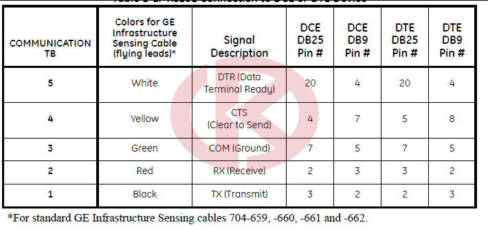
Wiring an RS232 Interface
Use the serial port to connect the Model AT868 flow transmitter to a
printer, an ANSI terminal or a personal computer. The RS232
interface is wired as Data Terminal Equipment (DTE), and the signals
available at the COMMUNICATION terminal block are shown in
Table 1-1 below.
1. Follow the instructions on page 1-4 to prepare the unit before you
connect power.
2. Use the information in Table 1-1 below to construct a suitable
cable for connecting the Model AT868 to the external device. If
desired, an appropriate cable may be purchased from the factory.
Wiring an RS485 Interface
Use the optional RS485 serial port to network multiple AT868 flow
transmitters to a single computer terminal. Upon request, the standard
RS232 port on the AT868 may be configured as a two-wire, halfduplex
RS485 interface, through a device such as the INMAC Model
800052 RS232-RS422/RS485 converter.
If the AT868 is configured at the factory for RS485 operation, the
INMAC converter is not necessary.
- AEROTECH
- MOOG
- ABB
- HIMA
- GE
- Prosoft
- EMESRON
- EPRO
- rockwell
- Technical Data
- Product Information
- Industry Information
- Company News
- DEIF
- Triconex
- UNIOP
- REXROTH
- Woodward
- Lumentum
- Honeywell
- National Instruments
- Bently Nevada
- MOTOROLA
- FOXBORO
- Enterasys
- KOLLMORGEN
- SIEMENS
- SST
- YOKOGAWA
- sieger
- RELIANCE
- meggitt
- VMIC
- ALSTOM
- EATON
- METSO
- Abaco
- HIRSCHMANN
- Rolls-Royce
- BENDER
- AMAT
- Brand
- ORMEC
- WATLOW
- Schneider
- PRAXIS-Automation
- BASLER
- Kongsberg
-
VESTAS CT318 VCS VCP MW Control Unit
-
TRACO POWER Industrial Power Supplies TIS600-128 115 / 230 VAC
-
AMAT 0010-32695 Controller instrument system
-
ELMO G-TUB30/480ERSS0 480VAC GOLD TUBA DIGITAL SERVO DRIVE
-
ELMO G-TUB30/480FEHSNA2 480VAC GOLD TUBA DIGITAL SERVO DRIVE
-
ELMO G-TUB30/230EESS0 30A/230VAC GOLD TUBA DIGITAL SERVO DRIVE
-
ABB SPCU1D50 Automatic voltage regulating module
-
ABB SPAU 341 C SPAU341C Voltage regulator
-
KONGSBERG RMP420-Remote Multipurpose Input/Output
-
ABB CBI 22-P EX 3BDH000732R1 Binary Input CBI22PEX
-
ABB CTI 21-P Ex 3BDH000741R1 16/32 Inputs Ex, Temp. Input, SW Versio CTI21PEx
-
WOODWARD SPM-D10/YB Synchronizing Unit
-
AEROTECH UNIDEX100 MOTION CONTROLLER U100i
-
ROLLS-ROYCE PE9002 HELICON-X3 ETHERNET SWITCH U7
-
ABB 3BSE013175R1 GRBTU-01 PR:C Module Terminal Unit
-
ABB CT-APS.22 1SVR630180R3300 Analog I/I Signal Converter
-
Safemaster BN5930 Safety Relay
-
ABB 3BHE009017R0102 VLSCD Board XVC724BE102
-
ABB 3BHL000986P0006 controller UNIT FPX86-9377-A
-
MR627 P89627-0-2333400-300-401-601-701schneider ELAU Servo Drive
-
LDMTR-01 63940135F ABB Inverter Contro
-
ABB CHBX01R 2VAA008575R1 BASE MODUL
-
ABB CHBX01L 2VAA008574R1 BASE MODUL
-
ABB RMU610 2VAA008425R1 BASE MODUL
-
ABB 3BUS208796-501 Controller unit
-
ABB HIEE205014R1 HI220856-312/20 UNC4673AV1 Analog Measuring Card
-
ABB P8151B TMR Analog Input unit
-
ABB P8403 TMR Analog Inpu
-
ABB P8431 TMR Analog Inpu
-
ABB PPD117A3011 3BHE030410R3011 central processing unit CPU module
-
ABB PPD512A10-454000 3BHE040375R103E Control unit
-
ABB RET670 1MRK002816-AC 670 series
-
ABB PFCL201CE 50KN 3BSX802939108 Horizontal force measurement
-
ABB LS4000 Diode laser analyzer
-
ABB G2000A5.7ST Used for excitation drive systems G2000A57ST
-
ABB PPD513AOC-100440 3BHE039724R0C3D 800 D513 Used for excitation drive systems
-
ABB XUD194 XUD194A 3BHC018137R0001 Used for excitation drive systems
-
ABB MT-91-ARC FP A Operator Panel RS232C 14-0V 60V 0,5A
-
ABB REC670 Relion 670 SERIES 670 series
-
ABB Bailey Infi90 SPSED01 Provides first 16 Digital Inputs
-
ABB UAD155A0111 3BHE029110R0111 matching capacitors are used for the excitation drive system
-
ABB CDP 312R CDP312R ACS800 AC Drive Control Panel Keypad 57619414 A 1/2
-
ABB system TPPB-02 card module
-
ABB Bailey Infi90 SPNPM22 Network Processing Module
-
ABB 3HAC17346-1/01 Rotational ac motor
-
ABB MNS iS MView Human Machine Interface 1TGE120020R0614
-
ABB UFC760BE145 3BHE004573R0145 content board
-
ABB GRID BREAKER UNIT VLM70 3BHE034262R0001 PCS6000
-
ABB 3BHL000986P controller UNIT FPX86-9364-A
-
ABB S-053M 3BHB012897R0003 ACS2000 The matching capacitors are used for the excitation drive system
-
ABB Inspirational system 3BHE050077R0102 UNS0881b-PV2
-
ABB HS810 3BDH000305R0101 connection device
-
ABB PF900-NR 3BDH000357 controller products
-
ABB KUC755AE101 3BHB005245R0101 Control System
-
Abb YPP110 digital processor module 3asd573001a1 YPP110A
-
ABB GMKP2800-32IBY The matching capacitors are used for the excitation drive system
-
ABB PS203PRESPMCPS Controller unit
-
ABB 216MB66 HESG324510M1 Controller products
-
ABB SPAJ140C Earth-fault relay
-
COMPRESSOR CONTROLS CORP 17-550555-001 IOC-555-D RS-485 Card
-
Woodward AMG2 Engine/Generator Controller LR21232
-
ALSTOM E64L1 high-performance power electronic device Professional service L54E1100EC00
-
ALSTOM CARD URVIC-54-322137 L54E2900TZ00
-
ALSTOM EXCITATION FAULT DETECTION, MODEL MDEX1 L54E2900XK00
-
ALSTOM POWER CARD FOR 3PHASE REGULATOR MODEL CPRT1 L54E1100BC00
-
ALSTOM ANALOG I/O CARD MODEL ESVI1 L54E1100BB00
-
ABB DISPLAY CARD ARTN1 L54E2901TW00
-
ABB DCF803-0050 3ADT209026R0001 Excitation unit module group
-
CONTROL MODULE – DRIVE UNIT 750203/806 100–250 V AC/DC ABB
-
Woodward ESDR4 Current Differential Protection Relay ESDR405-h0018B
-
ABB 3BHB007438R0001 WE-72-10/CH POWER UNIT 64421956
-
ABB B5LA HENF327886R0001 rackmount
-
ABB P7LA HNEF105323R0002 rackmount
-
ABB PPC322 BE01 PSR-2 processor + fieldbus HIEE300900R0001
-
ABB REF620C_F NCFNAAAAABC2DNN1XF Feeder Protection and Control
-
ABB P72140-4-0788740 CTI21 Temperature Input 16/ 32 Inputs
-
ABB DYTP123A 61430001-TW Control drive board
-
ABB DYSF118B 61430001-XG Control drive board
-
ABB CI535V26 3BSE022161R1 SPA Server protocol SPA Bus
-
ABB 1MRK002133-ABr02 RED670 I/O-modules 670 series
-
ABB 3BHB019265R0410 acs6000 Controller unit
-
ABB HIEE205012R0001 UNC4672A,V1:Analog Measuring Card
-
ABB REL561 1MRK002496-AC Protection Relay
-
ABB REL551 1MRK002480-AE Protection Relay
-
ABB RED521 1MRK002003-BA Protection Relay
-
ABB REC650 1MRK008514-CB Relion® 650 series
-
ABB RER103 Bus Connection Module
-
ABB REF545 KB133AAAA feeder terminal
-
GE IS200JPDFG1A DC INPUT 94 V DC DC POWER DISTRIBUTION MODULE
-
ABB Bailey Infi90 IMICV01 Servo Valve Interface Module
-
ABB 3ASC25H215E DATX131-equipped Torque observer board
-
ABB DASD001 3ASC25H241 mounted on Process I/O-board
-
ABB XVC768AE102 3BHB007211R0102 Board
-
ABB 531X306LCCBAG3 Communication Card
-
ABB NDCU-33CX 3AUA0000052751 Branching unit kit
-
ABB APBU-44C 4X KIT 68242371 Branching unit kit
-
ABB inverter mainboard terminal board NAMU-01C 64702475D
-
ABB L003748-AR 3BSX108237R300 mounted on Process I/O-board
-
ABB Communication Module COM0034 2RCA023019A0004C
-
ABB REU615E_D HBUAEAADNCA1BNN1XD Voltage Protection and Control
-
ABB S-113H 3BHB018008R0003 Power unit ACS 6000 System
-
ABB PM858 3BSE093350R1 Control unit
-
abb AI02J 16-CH with HART, Quick Response
-
ABB DSCA190V 57310001-PK communication module
-
ABB XVC768115 3BHB007211R115 Board
-
ABB DAPI100 3AST000929R109 mounted on Process I/O-board
-
ABB PCD530A102 3BHE041343R0102 UNITROL processor unit
-
ABB CMA130 3DDE300410 Basic Controller Panel Unit
-
ABB PCD237A101 3BHE028915R0101 UNITROL processor unit
-
ABB CI627A 3BSE017457R1 Communication Interface
-
ABB REF543 KB127AAAA feeder terminal
-
ABB PFCA401SF 3BSE024387R4 Control Unit Millmate 400
-
ABB HIEE401807R0001 CMC910A AMC3x Flash Memory Subboard
-
ABB UNITROL1005-0011 ECO 3BHE043576R0011 Drive
-
ABB XVC769AE101 3BHE006373R0101 Pulse transformer IGCT
-
ABB UFC765AE102 3BHE003604R0102 Pulse transformer IGCT
-
ABB CI930F 3BDH001010R0002 Communication Interface, PROFIBUS DP Master
-
ABB REM620A_F NAMBBABA33E5BNN1XF Motor Protection and Control
-
ABB 1TGE120010R... Rev.A controller unit
-
ABB Bailey NSSM01 Superloop Storage 6636896 AI 15VDC 27.4VA
-
ABB Bailey IEMPU02 Digital Input Module
-
NWX511a-2/R HESG112548R12 ABB controller system card
-
ABB IISAC01 Analog Control Station (SAC)
-
NTLS01 ABB Bailey Control and I/O TERMINATION UNIT
-
ABB 8025-235 Controller products
-
ABB Exchange PU512V2 3BUR001401R1 Real Time Accel. w/ DCN
-
ABB 216NG61A HESG441633R1 HESG216875 Controller products
-
ABB SCYC51020 58052582G Control Module


All new products and surplus products of the industrial intelligence industry, as well as the discontinued products of the original manufacturers. We are not an authorized distributor or representative of any of the above manufacturers (except for brand authorization). The trademarks, brand names and brands appearing in this agreement are the property of their respective manufacturers.
COPYRIGHT© 2003-2025 Copyrighted

Phone(WeChat/Whatsapp)
+086-181 4410 0983
No 1134 Jimei North Road,
Hong Kong Office:
Guan Tang District, Hong Kong,
