-
Products related to categories: servo, frequency conversion, HMI, driver, distributed DCS, IPC (PC bus industrial computer), PLC (programmable control system), DCS (distributed control system), FCS (field bus system), robot and other products and technical services.
-
Applications: Wind energy, automobile, ship, transportation, manufacturing, aviation, petroleum, natural gas, thermal power, thermal power, nuclear energy, steel, metallurgy, mining, power and other industries
-
Controller PLC\Robot servo drive Electro-hydraulic servo valve\DCS system/Distributed control systemSystem rack\Communication adapter\Analog output\Analog input\
-
\Multi-meter energy meter\Ignition\circuit board\Crimp terminal\Electric ac drive\Low voltage DC power module\Electro-hydraulic\servo valve\Automatic control system\exchange\Network communication module
controller\Processor module\dynamo\Electric machine\Servo drive\Touch screen\Input/output module\Water treatment monitoring system\Automobile\manufacturing system\Thermoelectric control system\ -
Digital output\Digital input\Mechanical protection system\High speed CPU
-
Electric power system\Chemical testing system\Petroleum control system\Tension monitoring system
-
DCS Distributed\control system\Steel control system\Steam\turbine system\Power generation system\
-
Thermal power generation system\Wind power system\Medium and high voltage frequency\conversion system\Precision motion system\Programmable control system\
-
Singapore New Energy Corporation
-
Geylang Bahru Industrial Estate
-
การทางหลวงแห่งประเทศไทย
-
American Petroleum Group
-
Indian shipping works
-
Pakistan Gas Company
-
Russian Automotive Industry Corporation
-
Brazilian Mining Company
-
Bangladesh Hydro power Plant
-
Egyptian Iron and Steel Manufacturing Co
-
Groupe d’exploitation du métro français
-
Für meinen vater
-
Mongolia Wind Farm
-
Empresa venezolana de procesamiento de petróleo
-
alibaba
-
Sichuan Huayingshan Power Plant
-
Huadian Datong Power Plant
-
Guodian Shuangyashan Power Generation Co., Ltd.
-
Baosteel Group Xinjiang Bayi Steel Co., Ltd.
-
Guodian Changzhou Power Plant
-
Xingtai Iron and Steel Co., Ltd.
-
Guodian Fee County Power Generation Co., Ltd.
-
Yangzhou Second Power Plant
-
Sichuan Jintang Power Plant
-
Xingcheng Special Steel Co., Ltd.
-
Quzhou Yuanli Metal Products Co., Ltd.
-
Zijin Mining Group
-
(Bangladesh) Metro Construction Company
-
WuHan steel co., ltd.
-
MaAnShan steel co., ltd.
Abaco VR12, VP12 6U VME Single Board Computer
This chapter describes features, capabilities, and compatibilities of the VR12 and
VP12 VME Single Board Computer (SBC). The two boards are based on the same
PCB. All further occurrences of the board’s names will be referred to as the VR12.
Any further specification in this document referring to VR12 can be applied to
VR12 and VP12 unless otherwise noted.
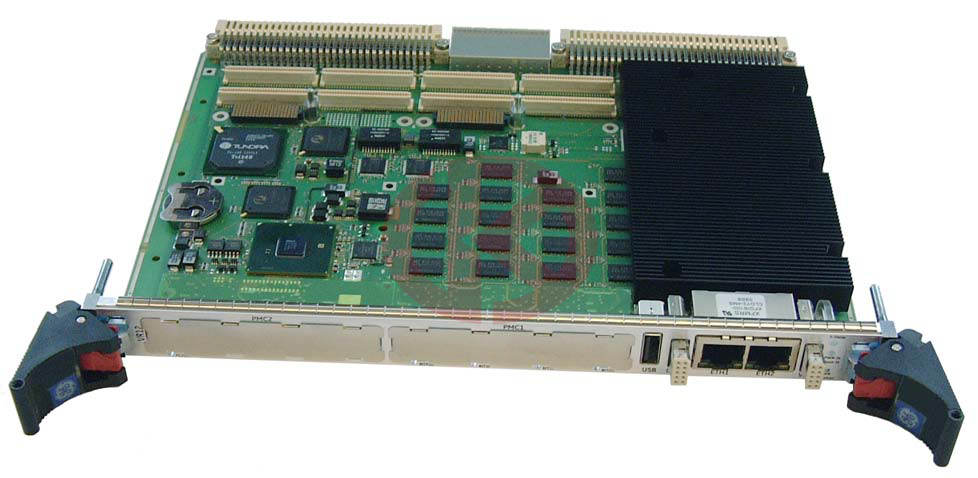
The VR12 is a fully IBM®-AT compatible stand-alone PC. It is equipped with
many functions a conventional Personal Computer can only offer after the
installation of several add-in cards. Extension boards can be connected via the
VME interface. The minimal board size and the large number of I/Os and
functions allow the VR12 to be used in many applications.
The VP12 is based on the VR12 but dual slot and provides with a mezzanine card
two hard disk bays. The usage of PMC2 and XMC2 is limited see description of
these interfaces.
See the following block diagram for the boards design.
The VR12 VME Single Board Computer features:
Microprocessor
Intel® Core™ i5/i7 mobile processor (up to 4 MB Level3 cache) with integrated
dual channel ECC Memory Controller, integrated graphic and PCIe channels
Supported CPUs
i7-610E 2.53 GHz 35 W SV (Standard Voltage)
i5-520E 2.4 GHz 35 W SV (Standard Voltage)
i7-620LE 2.0 GHz 25 W LV (Low Voltage)
i7-620UE 1.06 GHz 18 W ULV (Ultra Low Voltage)
Chipset PCH
Intel Series 5 Enhanced Mobile QM57 Peripheral Controller Hub (PCH)
with PCIe channels, SATA, USB, graphic ports, SMBus, LPC, SPI
PCIexpress
Seven PCIexpress links onboard, two XMC x8 slots
SDRAM
onboard soldered, two 72-bit channels, 1 GB to 8 GB DDR3 1066/800 MHz with
ECC
SPI Flash UEFI Firmware with Back-up UEFI Firmware
Easy updating, in-system programmable Flash ROM, automatic system
configuration, write protected Back-up UEFI Firmware with automatic swap
UEFI Firmware.
Integrated VGA, SATA RAID and Ethernet PXE ROM BIOS
USB mass storage support, password protection, headless support
remote console via serial port
EEPROM (Serial)
512 Kbit for user data via SMBus
CMOS RAM
242 byte non-volatile RAM for UEFI Firmware configuration storage
Hard/Flash Disk
Onboard mountable 2.5” SATA (3 GB/s) hard disk or FlashDrive.
Internal Flash Disk (NANDrive™)
Onboard soldered Flash Disk (NANDrive) connected via SATA-PATA controller
Floppy
Via USB
Serial I/O
Three asynchronous 16550 compatible full duplex channels with 16 byte FIFO.
Two COM ports at rear I/O, transfer rates up to 115.2 KBaud, user selectable
RS232/422/485 in UEFI Firmware setup. One COM port RS232 available at front
(not with conduction cooled levels D, E)
GPIO
12 GPIO input or output (10 GPIOs pins shared with DVI1; GPIO(0..9) and DVI1
exclude each other)
Write Protection
Hardwire Write Protection of all non-voltage memories, UEFI Firmware flashes,
User EEPROM, Flash Disk (NANDrive), Config EEPROMS of PCI bridges and
Ethernet controllers
PMC slots
PMC1 and PMC2 with 64 bit/133 MHz PCI-X (3.3 V IO voltage signaling only);
PCI mezzanine connector for standard PMC with front and rear IO. IO signals are
available at the rear connectors.
Compliant to ANSI/VITA 20-2001
Non-Monarch option compliant to ANSI/VITA 32-2003
PMC front I/O not available in conduction cooled
PMC bus is not available if a XMC card is installed
XMC slots
Two XMC slot at the PMC location with x8 PCIe lanes each. The PCIe lanes for the
XMC are shared with PCIe for the PMC-PCI bridges. If a XMC module is installed
the PMC/PCI part is disabled.
VMEbus
PCI bus to VMEbus controller, up to 60 MByte/s transfer rates
FIFOs for write posting, DMA controller with linked list support
Geographical addressing
VMEbus system controller
Master (including RMW) and Slave (including RETRY*) transfer modes:
BLT, ADOH, RMW, RETRY
A64 / A32 / A24 / A16
D64 (MBLT, 2eVME, 2eSST) / D32 / D16 / D8 (SCT, BLT)
IPMI Controller
Hitachi controller for support of Intelligent Platform Management Interface.
Implementation according to VITA 38.
Temperature Sensors
Integrated sensors which measure the temperatures of the CPU and PCH dies and
in the SuperI/O device for board temperature. The CPU die sensors are software
readable in 1 °C increments from 0 °C to +105 °C, the PCH sensor from 59 °C to
125 °C.
Front panel I/O
2 x GigE, VGA2, PMC1 or XMC1, PMC2 or XMC2, USB, Power Button,
LEDs for boot-up and power status indication red/amber/green and four LEDs for
BIT status.
For restrictions or conditions see appropriate chapters in this manual
Rear I/O
Via Transition Module VTM24
DVI1, DVI2, VGA1, SATA 4-5, (SATA2-3 please ask factory), COM1-2, two USB,
PMC1 I/O and PCM2 I/O, GPIO [0...11], Write Protection, two status LEDs, 2x
GigE, Power Button
For restrictions or conditions see appropriate chapters in this manual
Software
Windows®, Linux®, VxWorks®, Solaris®, Integrity (on request)
- AEROTECH
- MOOG
- ABB
- HIMA
- GE
- Prosoft
- EMESRON
- EPRO
- rockwell
- Technical Data
- Product Information
- Industry Information
- Company News
- DEIF
- Triconex
- UNIOP
- REXROTH
- Woodward
- Lumentum
- Honeywell
- National Instruments
- Bently Nevada
- MOTOROLA
- FOXBORO
- Enterasys
- KOLLMORGEN
- SIEMENS
- SST
- YOKOGAWA
- sieger
- RELIANCE
- meggitt
- VMIC
- ALSTOM
- EATON
- METSO
- Abaco
- HIRSCHMANN
- Rolls-Royce
- BENDER
- AMAT
- Brand
- ORMEC
- WATLOW
- Schneider
- PRAXIS-Automation
- BASLER
- Kongsberg
- DISCO Corporation
-
ABB NINT-73C Drive control mainboard NINT73C 64425579A
-
BASLER DECS-250-CN1SN1N Digital Excitation Control System DECS250CN1SN1N
-
GE IS420ESWAH3A 8-port 10/100 base copper only
-
IS420ESWAH1A 8-port 10/100 base copper with one 100 Mbps
-
GE IS420ESWAH2A 8-port 10/100 base copper
-
GE IS420ESWBH1A 16-port 10/100 base copper with
-
GE PQMII-T20-C-A Power Quality Meter
-
GE Mark VI IS230PCAAH1A/B Combination module unit
-
ABB 3BHE021887R0101 UBCC717BE101 Board 3BHB002751R0102
-
ABB 3BHE032593R0001 Isolated Power Supply
-
ABB 3BSC610023R0001 POWER SUPPLY SD812
-
Sleeve matching ABB PFSC230 3BSE081054R1, 25M
-
ALSTOM 029.204431 Power unit module Accessory Mainboard
-
ALSTOM Converteam 029.302250 Power unit module
-
GE IS420UCSBH1A Mark Vle UCSC Controller
-
GE EX2100e Power Conversion Module 151X1235DB15SA1
-
MOOG G122‑829A P-I SERVO AMPLIFIER
-
S-D4017 Remote IO Backplane SSBP-1 RELIANCE drive module
-
CC-link card CCLK-1 S-D4030 RELIANCE drive module
-
Digital IO card DIO-1 S-D4006 RELIANCE drive module
-
S-D4041 DSPM-2A DSP RELIANCE drive module
-
abb 3BUS208720-001 POWER SIGNAL INTERCONNECT
-
GE DS3800NB1A Control Drive Board Serial Port Terminal Board
-
ABB EI813F 3BDH000022R1 communication card
-
TMEIC KPAD-3122A A3XAP02 LCD Display With Key Drive Accessories
-
ALSTOM F425368001 Rupture Disc 110 kV Gas Insulated Switchgear
-
80190-219-01G Allen Bradley Driver Pcb Board IGCT
-
GE DS3815PAHB1A Control Unit Drive Board
-
GE Mark VI IS230JPDGH1B Combination module unit
-
ABB 1MRK002247-Apr04 I/O-modules 670 series
-
ABB 0769143 A CELL SAMPLE AL175MM Gas analyzer accessories
-
RS NX700 Series Controller OEMAX SAMSUNG NX-Y64T
-
RS NX700 Series Controller OEMAX SAMSUNG NX-Y32T
-
NX700 Series Controller OEMAX SAMSUNG NX-X64D 64 output
-
NX-X32D 32 output Series Controller OEMAX
-
NX700 Series Controller OEMAX SAMSUNG NX-POSI4
-
NX-MWLINK Series Controller OEMAX SAMSUNG
-
RS NX-ETHERNET Series Controller OEMAX SAMSUNG
-
NX700 Series Controller OEMAX SAMSUNG NX-DEVICE
-
a-b NX700 Series Controller OEMAX SAMSUNG NX-CPU760C
-
NX700 Series Controller OEMAX SAMSUNG NX-BASE12
-
RS NX700 Series Controller OEMAX SAMSUNG NX-AO4V
-
NX700 Series Controller OEMAX SAMSUNG NX-AI8V
-
PowerFlex® 7000 ForGe Drives which utilize the new HMI Interface Board 80190-780-01-R
-
GCU-08 CB-130 80173-109-01-3 Mitsubishi Thyristor Inverter Power Board
-
a-b 1769-L30 CompactLogix 5370 L3 Controllers
-
A-B MicroLogix™ 1762-OW16 Relay Output Module
-
A-B 1761-ENT-AIC advanced interface converter
-
1761-CBC-PM02 ControlLogix Redundancy System cable
-
A-B 1746-IV16 16DI 10-30V DC SOURCE MODULE SLC 16 Digital Inputs
-
A-B 1746-IB16 module Rockwell SLC 16-point digital input control
-
A-B 1734-MB Memory system memory card
-
A-B 1336-BDB-SP4D 74103-244-54 1336 PLUS II Servo drive power board
-
RELIANCE 0-60067-1 0-60067 Automax Drive Board 0-60067-A
-
RELIANCE 0-60066-1 0-60066 S0-60066 Automax Drive Board
-
Meggitt C327845-11 Flow shutoff valve -7 -5 Parker
-
Driver board 029.204 686 Alstom power unit
-
ABB 3BSE020828R1 DSAI130DK01 Combined analog input module
-
ABB SCC-C 23070-0-101142100000 Continuous Emission Monitoring System (CEMS) Sample gas cooler
-
Siemens 6SE7038-6EK84-1JC2 Inverter Gate Triggering IGD8
-
GE IS200AEPBH1BBA Fan power generation power board
-
ALSTOOM MVS3000-4001 Handheld controller unit
-
PILZ 630613 PSEN OP 4H-S-30-060 Light Curtain Receiver
-
schneider SQUARE D POWERLOGIC CM4250 CIRCUIT MONITOR 96ma
-
EATON E84BAN Crane Control Heavy Duty Mill Limit Switch 2200 VAC 2NO-1NC Contact
-
MVI56 PDP-MV1 ALEN-BRADLEY PROSOFT PROFIBUS UNIT MVI56PDPMV1
-
ABB SCC-C Sample gas cooler 23070-0-10211110
-
GE PN.246B9953BPG1 TOOL-SCR REMOVAL
-
GUTOR BY SCHNEIDER ELECTRIC OP2446 MAIN PROCESSOR BOARD
-
HONEYWELL FX-USI-0002 Universal Safety Interface Module
-
HONEYWELL TA3840S Communication Unit
-
ABB 19P123085397 PDD AVR Unit
-
EMERSON 5X00899G01 Ovation™ Power Supply System
-
ABB 5SHY3545L0020 3BHE014105R0001 5SXE05-0154 IGCT Module
-
4TB5203-0402 Liquid crystal display panel
-
ABB 3BHE036348R0101 Expansion bracket card
-
ABB 3BHE017400R0101 PPD104 Extended memory card
-
ABB 3BHE012049R0001 Fiber Optic Expansion Motherboard
-
ABB 3BHE006805R0001 High Voltage Inverter Motherboard
-
ABB 3BHE000412R0101 INU INTERFACE BOARD
-
ABB UCD208A101 3BHE020018R0101 control board card
-
ABB 3ADT309600R0012 SDCS-CON-2 Terminal UNIT
-
80190-480-01-R Allen Bradley Driver Pcb Board
-
ABB DSMB179 57360001-MS MEMORYBOARD
-
ABB DSMB178 57360001-MM MEMORYBOARD CATALOG DESCRIPTION
-
ALSTOM C264MB1D69500130A300000C000N10 micom C264 ds agile bay controller
-
ABB PFSK138 3BSE014292R1 Channel Control Unit PFSK 138
-
GE ALSTOM 029.380 896 Board Logical control 029380896
-
ABB S-123H 3BHB030479R0112 Power unit ACS 6000 System
-
GE PLB029-376433 Phase-controlled control module of gas compression unit
-
GE IGBT ProX690-1E1-0L0H1 Phase-controlled control module of gas compression unit PLB029-370338
-
GE Industrial System Mark V Display MMI 323A2374P2
-
VMEBUS RACK VME32 BACKPLANE 100-240V/50-60 Hz/1200W
-
IBA ibaLink-SM-128V-i-2oVMEbus Interface Board SM128V
-
VMIC VME-PMC-CADDY VME-Carrier Board for 2 PMC Modules
-
ABB REF620E_1G Feeder Protection and Control
-
ABB SACO16D1 Digital Annunciator Unit
-
ABB REF620 HBFNACNNNEA1BNN11G Feeder Protection and Control
-
GE UT150-2 CPU MODULE CARD FOR CE2000 CONTROLLER
-
ALSTOM TANSFORMER MAINTENANCE KIT 1000KVA UTHC GEC
-
ABB DASD146 3ASC25H270 Lifter controller accessories DASD145
-
ABB DASD147 3ASC25H280 Lifter controller accessories DASD107
-
ABB SCC-K Converter NO2/NO converter and Thermal converter 3KXG801000U0100
-
Siemens 6AV6643-0CD01-1AX1 SIMATIC MP 277 10" Touch
-
ABB UAC095AE01 HIEE300788R0001 Communication Control IO Board
-
ABB AC800PEC Measuring Interface PECMIUAD140 PECMI UA D140
-
ABB 500PSM03 1MRB150038 Power Supply module
-
Valmet metso D201563L Control unit accessories
-
Valmet metso D201473L AII8 Control unit accessories
-
EATON XVS-430-10MPI-1-10 Touch panel 24 V DC TFTcolor, ethernet, RS232
-
bently 60M100-00 Condition Monitoring System
-
ABB 3BHB004791R0101 IGCT Gate Power Supply Unit
-
ABB TAS.580.0550.G00 HARDWARE BOARD ABB100 COMPONENTS SIDE
-
ABB SYN5201A-Z,V277 3BHB006714R0277 Automatic single-channel synchronization unit
-
ABB SUE3000 1VCF750090R0804 Operation screen unit 1VCR007346
-
ABB SENSYCAL FCU400-IR Product Summary
-
ABB SDCS-CON-2-COAAT 3ADT220090R2 DCS Thyristor Power Converters accessories
-
ABB SCYC51220 63901075c Control Module
-
Siemens SYNCHRONOUS SERVOMOTOR 1FK6084-6AZ21-9ZZ9-Z S05
-
Siemens SYNCHRONOUS SERVOMOTOR 1FK6063-6AF71-1EH0
-
FOXBORO FBM241/b/c/d Discrete I/O Interface Modules
-
FOXBORO FBM242, Externally Sourced, Discrete Output Interface Module
-
FOXBORO FBM244, 0 to 20 mA I/O Interface Module with HART Support
-
FOXBORO FBM245, 0 to 20 mA I/O Interface Module with HART Support
-
FOXBORO FBM247, Current/Voltage Analog/Digital/Pulse I/O Configurable Interface Module
-
FOXBORO FBM218 HART Communication Redundant Output Interface Module
-
FOXBORO FBM219 Discrete I/O Interface Module
-
FOXBORO FBM222, Redundant PROFIBUS Communication Interface Module


All new products and surplus products of the industrial intelligence industry, as well as the discontinued products of the original manufacturers. We are not an authorized distributor or representative of any of the above manufacturers (except for brand authorization). The trademarks, brand names and brands appearing in this agreement are the property of their respective manufacturers.
COPYRIGHT© 2003-2026 Copyrighted

Phone(WeChat/Whatsapp)
+086-181 4410 0983
No 1134 Jimei North Road,
Hong Kong Office:
Guan Tang District, Hong Kong,
